Defining the Geometry
Just like a preset shape, a custom shape has a position and a shape bounding box that is specified by the offset and extent transform values. The shape coordinate system is defined by these values as was described in section 1.2 above. The path coordinate system is also partially defined by these in that it has it’s width and height set by these values. The units of the path system however are determined by the specified width and height of the path.
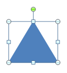
A custom shape with a single path can be specified using the following DrawingML code.
<p:sp>
  <p:spPr>
    <a:xfrm>
      <a:off x="3200400" y="1600200"/>
      <a:ext cx="1200000" cy="1000000"/>
    </a:xfrm>
    <a:custGeom>
      <a:pathLst>
        <a:path w="2" h="2">
          <a:moveTo>
            <a:pt x="0" y="2"/>
          </a:moveTo>
          <a:lnTo>
            <a:pt x="2" y="2"/>
          </a:lnTo>
          <a:lnTo>
            <a:pt x="1" y="0"/>
          </a:lnTo>
          <a:close/>
        </a:path>
      </a:pathLst>
    </a:custGeom>
  </p:spPr>
</p:sp>
As can be seen in the above code, the path has a width and height of 2. This means that the path coordinate space will have units of (1/2 * shape width) for x-coordinate and (1/2 * shape height) for the y-coordinate. Thus we see that a coordinate of (2,2) in the path coordinate system will be the same as (1200000,1000000) within the shape coordinate system.
To define the shape path above we can see that there are a few different parts to defining this custom shape. The first is to define the first path in what is called the path list. It should be noted that the path list can have multiple paths in it, some filled, some not, some outlined, some not. To define the path we must specify the width, height and thus units for this path via the following DrawingML.
<a:path w="2" h="2">
This sets up the path coordinate system for this path as was previously described. Next we need to move the drawing cursor to the point in this path coordinate system that we wish to start drawing our shape from. The following DrawingML does just that.
<a:moveTo>
  <a:pt x="0" y="2"/>
</a:moveTo>
This will move the drawing cursor to the bottom left position (0,2) which is equivalent to (0,1000000) in the shape coordinate system. Following this we can now start by drawing the first line in the shape via the following line.
<a:lnTo>
  <a:pt x="2" y="2"/>
</a:lnTo>
This will draw a line from the current drawing cursor position of (0,2) to (2,2) which is the bottom right corner of the path coordinate system. This is equivalent to drawing a line from (0,1000000) to (1200000,1000000) in the shape coordinate system. Now that we have the bottom edge of the triangle drawn we can continue to the final edge in the shape via the following.
<a:lnTo>
  <a:pt x="1" y="0"/>
</a:lnTo>
This will draw the final line that will be drawn from the current drawing cursor position of (2,2) to (1,0) which is in the top middle of the path coordinate system. This is equivalent to drawing a line from (1200000,1000000) to (600000,1000000) in the shape coordinate system. Now that most of the triangle has been drawn. It should be noted that since the <<close/>> element is specified at the end of the path that a line will be drawn from the last point in the path back to the first point in the path. This explains a bit of the existence of the following final element.
<a:close/>
This finalizes the edges of the shape path being specified. Since the fill of this path is set to normal, this path will have a fill no matter if this close tag is specified or not. However, the fact that it is specified determines that there will be a final edge drawn between the final drawing cursor point and the path starting point. Now that the path has been fully specified, this shape can be filled and thus be considered finished.