Timeline Construction
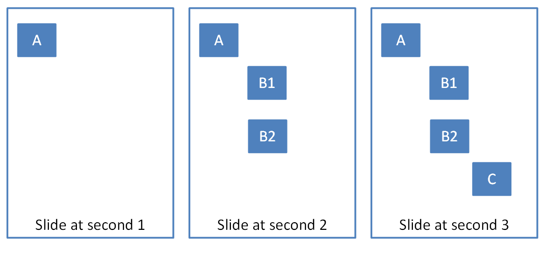
To illustrate what the timeline looks like in the slide XML file, suppose we have four rectangles named A, B1, B2, and C that appear on a timeline three seconds long. Rectangle A appears at second 1, B1 and B2 appear together at second 2, and C appears at second 3, as shown below:

The timeline and time containers could look something like:

A typical timeline consists of the following structure:
<p:timing>
  <p:tnLst>
    <p:seq concurrent="1" nextAc="seek">
      <p:stCondLst> …
      <p:cTn id="2" dur="indefinite" nodeType="mainSeq">
        <p:childTnLst>
          <p:seq> …   // Square A
          <p:seq>
            <par>….   // Square B1
            <par>….   // Square B2
          </p:seq>
          <p:seq> …   // Square C
        </p:childTnLst>
      </p:cTn>
      <p:prevCondLst> …
      <p:nextCondLst> …
    </seq>
  </p:tnLst>
  <p:bldLst> …
</p:timing>
As show, this timeline starts with a <timing> element that represents the timeline. Within this timeline, there is a child element <tnList,> which contains a list of time nodes.
In this case, there is one main timing container, which is the <seq> element. Within this element there are a three of conditional elements, namely <stCondList>, <nextCondList>, and <prevCondList>. These elements contain condition properties that allow for the starting/stopping of the particular time node. This is explained in more detail in §4.4.6.
Following the <stCondList >element is the <cTn >element, which describes the properties for this node. Within this element is the <childTnList,> which contains the nested time nodes that describe the animation sequence mentioned above.
Finally, we have the <bldList >element, which is used to specify how objects with sub-shapes should be animated. More information can be found in §4.4.7.